|
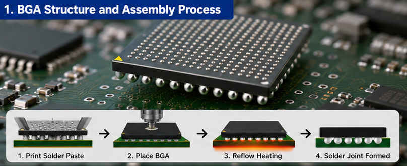
Introduction Ball Grid Array (BGA) packages have become ubiquitous in modern electronics. They offer high I/O density, excellent thermal and electrical performance, and a compact footprint. However, BGAs also present unique assembly challenges. The solder balls are hidden under the component body, making inspection difficult. The large thermal mass can cause warpage during reflow. And a single poor joint can scrap an entire board. This article covers the essential aspects of BGA assembly: component handling, placement accuracy, reflow profiling, and common defects. Whether you assemble fine-pitch BGAs on smartphone mainboards or large body BGAs on automotive electronics, these principles apply. What Makes BGAs Different Unlike components with visible leads (QFPs, SOPs), BGAs have an array of solder balls on the bottom surface. The component is placed onto solder paste, and during reflow, the balls melt and collapse onto the PCB pads.
Key differences from standard components:
Common BGA package types:
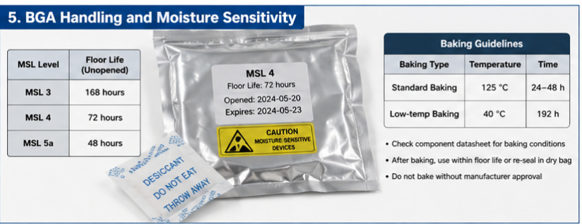
BGA Handling and Moisture Sensitivity Most BGAs are moisture-sensitive. They absorb moisture from the air, and during reflow, trapped moisture turns to steam and can crack the component internally. This is called "popcorning." MSL ratings for BGAs: Typically MSL 3, 4, or 5a (see previous article on MSL). Handling rules:
Baking guidelines:
BGA Placement Considerations Placement accuracy requirement: BGA placement is more forgiving than fine-pitch QFPs because surface tension during reflow pulls the component into alignment. However, there are limits.
Placement force: BGAs are heavy. Excessive placement force can squeeze paste out from under the component, causing bridging. Insufficient force may not seat the component properly.
Vision alignment: Most pick-and-place machines use one of two methods for BGA alignment:
Recommendation: Use ball recognition for fine-pitch BGAs (0.5mm and below). Use body recognition for large-pitch BGAs where placement tolerance is wider. Solder Paste for BGAs BGA assembly requires paste that can:
Paste selection considerations:
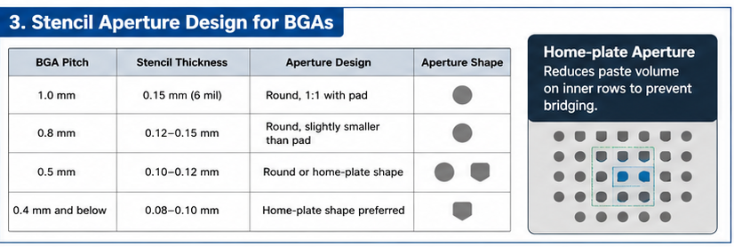
Stencil design for BGAs:
Home-plate aperture: A pad shape that reduces paste volume on the inner rows of a BGA. This compensates for the tendency of inner balls to bridge due to paste squeeze-out.
Reflow Profiling for BGAs BGAs have large thermal mass. They heat up more slowly than small passives on the same board. This thermal lag is the biggest challenge in BGA reflow. Key considerations: 1. Delta T across the BGA The temperature difference between the center and edge of a large BGA can be significant during reflow. If one side melts before the other, the component can warp (dynamic warpage), causing head-in-pillow or open joints. Target: <5°C delta T across the BGA during time above liquidus (TAL) How to achieve:
2. Time above liquidus (TAL) BGA balls need sufficient time to fully collapse and wet to the PCB pads. Typical TAL for BGAs: 60-90 seconds (compared to 45-75 seconds for standard components) 3. Peak temperature The BGA body temperature must reach the paste melting point, but not exceed the component's maximum rating. Typical peak for lead-free: 235-245°C (check BGA datasheet – some BGAs have lower maximums) 4. Ramp rates Slow ramp rates reduce the risk of BGA warpage and moisture damage. Recommended ramp rate: 1.5-2.5°C/s (slower is safer for large BGAs)
Common BGA Defects and Causes Head-in-Pillow (HiP) The BGA ball melts but does not collapse into the solder paste. The joint looks like a ball sitting in a shallow depression – the "head" on a "pillow." Causes:
Prevention:
Voids Air pockets trapped inside the solder joint. Small voids are generally acceptable; large voids reduce mechanical strength and thermal conductivity. Causes:
Acceptable void limits (IPC-7095):
Prevention:
Bridging Solder connects two adjacent balls. Causes:
Prevention:
Open Joint (Ball Not Connected) A ball fails to wet to the PCB pad. Causes:
Prevention:
BGA Rework – When Things Go Wrong BGA rework requires specialized equipment and training. It is not recommended for inexperienced operators. Basic rework process:
When to reball vs. replace:
Rework success rate: With proper equipment and training, 90-95% first-pass rework success is achievable. Without proper equipment, expect 50% or less.
X-Ray Inspection for BGAs Because BGA joints are hidden, X-ray inspection is essential for process validation and quality control. (See next article for detailed X-ray guidance.) What X-ray reveals:
Inspection frequency:
BGA Design for Assembly (DFA) Tips Problems that start in design cannot be fixed in assembly.
Conclusion BGA assembly is challenging but manageable with proper process control. Focus on four areas:
The most common BGA defect – head-in-pillow – is almost always a reflow problem (warpage or insufficient TAL) or a paste problem (weak flux). Solve those, and most BGA issues disappear. Invest in good reflow profiling with multiple thermocouples on BGAs. And if you assemble BGAs regularly, X-ray inspection is not optional – it is essential. |
BGA Assembly Essentials – From Placement to Reflow
May 27, 2026 ETON